
PIEZO-STRAIN GAUGE SAMPLE HOLDER

Fig. 1 Picture of fabricated piezo-strain gauge sample holder: (a) top view with indicated components, and (b) bottom view with indicated strain gauge.
In order to perform inelastic light scattering studies and scanning probe microscopy based experiments of samples under uniaxial strain, within Strained FeSC project we designed, developed and fabricated a piezoelectric-based device. For that purpose, we followed designs of similar devices for applying continuously tunable uniaxial strain that had been devised, successfully used, and publicly available [1,2]. These designs were adapted for the purposes of inelastic light scattering and scanning probe microscopy base experiments, having in mind the compatibility with the available and the cryostat that will be procured.
Picture of the fabricated sample holder is displayed in Fig. 1(a). As can be seen, the device consists of three piezoelectric stacks connected with a bridge. Wires are used in order to apply bias voltage on the piezoelectric stacks. When the inner piezoelectric stack is extended (in the direction opposite to the bridge), the moveable sample plate is pushed toward the fixed sample plate which results in sample compression. On the other hand, when two external piezoelectric stacks are extended (in the direction toward the bridge), the whole bridge and the moveable sample plate are moved from the fixed sample plate, thus resulting in a sample extension. In order to follow and measure applied strain on the piezoelectric stacks, appropriate strain gauge was glued between fixed and moveable sample plate as depicted in Fig. 1(b).
The fabricated sample holder was placed in a cryostat (Fig. 2(a)) and further connected in an appropriate electronic circuit (Fig. 2(b)) in order to apply bias voltages needed for piezoelectric stacks and to measure applied strain. The piezoelectric stacks are connected with an analogue high power electrical amplifier. Its input is in the range 0-5 V, whereas at the output it gives 150 V needed to extend/compress piezoelectric stacks. In order to measure changes in resistance, the piezo-strain gauge is connected in Wheatstone bridge. In order to supply 5 V to the Wheatstone bridge and the analogue high power electrical amplifier, we used 7805 voltage regulator.
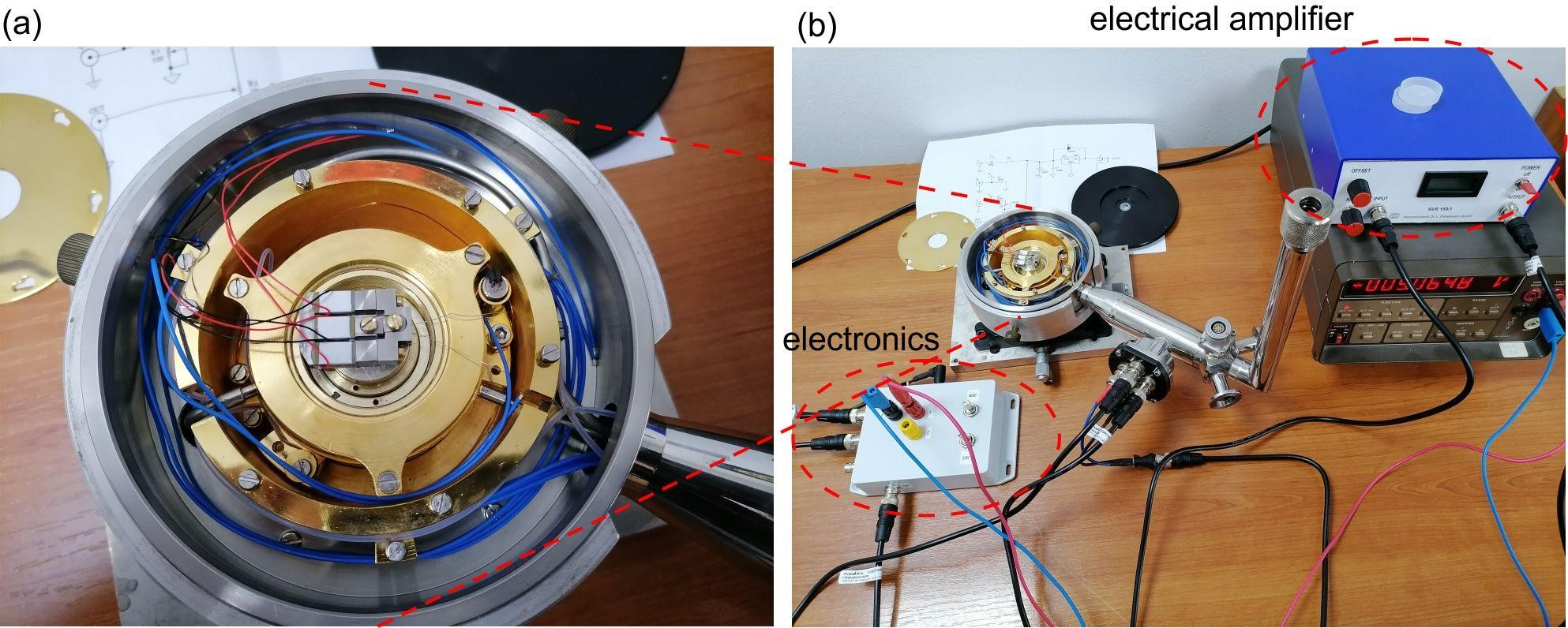
Fig. 2 Picture of the piezo-strain gauge sample holder in cryostat and connected with electronics.
Simple electronic scheme is given in Fig. 3. The voltage regulator 7805 gives 5 V at the output additionally filtrated with indicated capacitors. The variable resistor R4 is used in order to adjust bias voltage at OUT port needed for the amplifier. The strain gauge can be connected within points A and B, while the strain resistance can be simply measured as Rst=R1*V/(U-V), where U=5V (obtained from 7805 voltage regulator), whereas V is the voltage measured on the strain gauge. Additional option is to place strain gauge within the Wheatstone bridge.
The results of the first test measurements are illustrated in Fig. 4. The bias voltage applied on the external piezo-stacks was swept in the range 0-100 V. Simultaneously, we measured strain gauge resistance. Figure 4 depicts results for three bias voltages: 1 V, 50 V and 99 V. The resulting strain gauge resistance is 352.31 Ω, 352.86 Ω, and 353.25 Ω. Therefore, the test proves that the piezo-stacks extend with applied bias voltage leading to increased strain gauge resistance.
Further optimization is ongoing based on the specific experimental requirements.
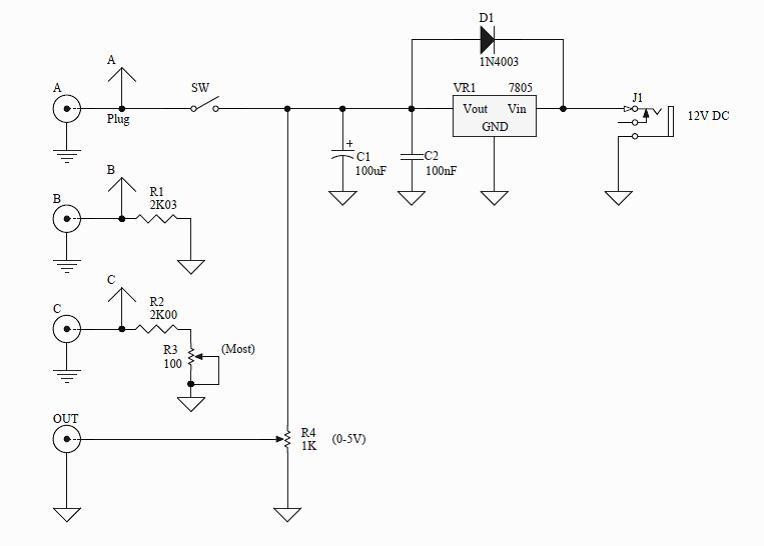
Fig. 3 Electronic scheme: the power supply for the Wheatstone bridge and the analogue high power electrical amplifier needed for the piezoelectric stacks.

Fig. 4 Test results: strain gauge resistance as a function of the bias voltage applied on two external piezo-stacks.